To install MV cable to SEC standards, work through five stages in order: (1) plan and document, (2) prepare the trench or duct, (3) pull within tension and bending limits, (4) make terminations and joints with certified kits, and (5) ground, bond, and test before energizing. The cable must meet SEC 11-SDMS-03, which covers XLPE insulated power cable rated 15 kV to 36 kV.
MV cables rarely fail because of the cable. CIGRE field data attributes around 80% of early failures to installation defects at joints and terminations (CIGRE), which makes workmanship the whole game for the engineers, jointers, and EPC teams handling mv cable installation in Saudi Arabia. This guide breaks down every stage, mapped to the SEC SDMS standards, so the line passes inspection and survives its design life.
The SEC Standards You Must Follow
Start with the documents, because SEC acceptance is document driven. The cable is governed by 11-SDMS-03 and the accessories by 12-SDMS-01, both under SEC SDMS standards. These standards localise international requirements, primarily IEC 60502-2 Installation shall be carried out in accordance with the approved method statement and project drawings.
| SDMS specification | What it controls | Why it matters to you |
|---|---|---|
| 11-SDMS-03 | XLPE insulated power cable, 15 kV to 36 kV | The cable you may install |
| 12-SDMS-01 | Cable joints and terminations | Kit, shrink, and adhesive rules |
| 12-SDMS-02 | Lugs and connectors | Low resistance connections |
| 01-SDMS-01 | General requirements | Quality and traceability |
Note: adapted from Saudi Electricity Company SDMS, Rev. 02.
Before You Start: Plan and Paperwork
You cannot start cable pulling until the document pack is complete. SEC inspectors review paperwork before inspecting site work, so prepare all documents in advance.
Documents SEC Inspectors Want
Prepare the following documents before mobilization:
- Manufacturer test certificates
- SEC-approved Material Approval Request (MAR)
- Cable pulling tension calculations
- Valid splicer certificates
Splicers must be certified by the manufacturer of the selected cable joint kit. Also verify cable sizing with a wire size calculator and check voltage drop before placing the order.
Prepare the Cable for Heat
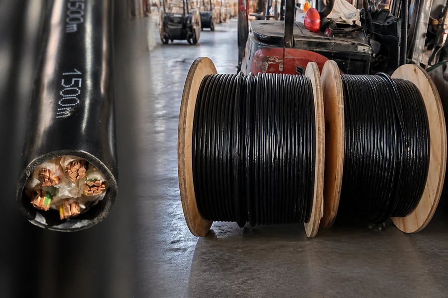
Store cable drums upright with end caps installed. This protects XLPE insulation from heat and prevents moisture ingress during Saudi summer conditions. Keep cable ends sealed until jointing work begins.
Step 1: Prepare the Trench or Duct Route
Start with a clean and approved route. The trench or duct protects the cable throughout its service life, so poor preparation can damage the outer jacket during installation. Trench depth, sand bedding, and cable cover must follow the project drawings and approved trench detail. For MV direct burial cable, the depth is often around one metre, but the approved detail is the final reference. Before pulling the cable, remove sharp stones, prepare bedding above and below the cable, install warning tape, and maintain safe separation from other underground services.
Local trench depths, grid connection rules, and installer requirements may vary by utility and project type, so confirm against the project drawings and the latest SEC specification.

For low-voltage feeders on the same site, armoured cable suits direct burial, such as the steel tape armoured N2XBY (YJV22) and steel wire armoured N2XRY (YJV32).
Step 2: Pull the Cable Safely
Safe cable pulling depends on proper tension control, bend control, and the right pulling accessories. Before starting, calculate the expected pulling force and confirm it is within the cable manufacturer’s limit.
Estimate the Pulling Tension
For a straight horizontal MV cable pull, pulling tension can be estimated as:
T = w × L × f
| Symbol | Meaning |
|---|---|
| T | Pulling tension |
| w | Cable weight per metre |
| L | Pulling length |
| f | Friction coefficient |
Example: 5 kg/m × 200 m × 0.3 = 300 kgf, or about 2.9 kN.
Compare the result with the maximum allowable tension in the manufacturer datasheet. A pulling eye fixed to the conductor usually allows higher tension than a grip on the sheath.
Keep SWBP Under the Limit
SWBP is the pressure created at bends. It can damage the cable even when the pulling tension looks acceptable.
SWBP = T / r
A smaller bend radius creates higher pressure. Keep SWBP below the manufacturer or project limit, and recalculate tension at every bend.
Hold the Bending Radius
Respect the minimum bending radius: a larger pulling value under tension and a smaller training value for final dressing. Use rollers and quadrants at bends, fit an anti twist pulling head, and use approved cable lubricant.
| Cable type | Minimum bending radius (typical) | Confirm against |
|---|---|---|
| Single-core MV, unarmoured | about 15 x cable OD | manufacturer datasheet / SEC project spec |
| Multi-core MV, unarmoured | about 12 x cable OD | manufacturer datasheet / SEC project spec |
| Armoured MV | about 15 x cable OD | manufacturer datasheet / SEC project spec |
Note: typical values; the exact minimum bending radius follows the manufacturer datasheet and the SEC project specification.
Step 3: Terminations and Joints
Terminations and joints decide cable life. Only certified workers should install them, following SEC 12-SDMS-01 and the kit manufacturer’s method.
| Item | Requirement |
|---|---|
| Cable preparation | Use scoring tools, not knives |
| XLPE insulation | No cuts or nicks |
| Shield cutback | Clean, even, and aligned |
| Joint system | Heat-shrink or cold-shrink complete kit |
| Manufacturer | One complete kit from one maker |
| Lugs | Copper for copper, bi-metallic for aluminium |
| Crimping | Calibrated tools only |

ANPU's N2XY power cable uses the same XLPE insulation system, so clean stripping matters on every voltage class.
Step 4: Grounding and Bonding
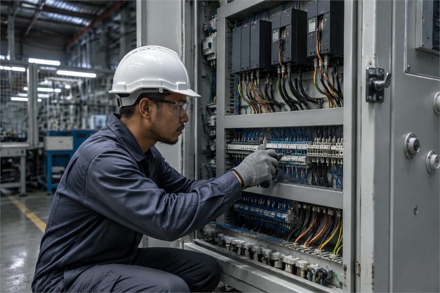
Bond the metallic screen so faults and induced currents have a safe path. Poor metallic screen bonding is a frequent inspection failure. Bond the screen at the correct points, including intermediate joints, with an adequate bare copper bonding lead. Mechanical connectors or constant force springs are preferred, since soldering can damage the insulation. For sizing earth and bonding conductors, the EGC Ground Wire Sizing Chart: 2026 NEC Guide helps, though the project spec governs.
Step 5: Testing and Commissioning
Separate factory tests from field tests. Factory tests prove the cable quality. Field tests prove the installation quality.
Factory Tests
Check the manufacturer test certificate. Under 11-SDMS-03, the cable should pass routine tests, including factory partial discharge testing. At 1.73 Uo, PD must not exceed 10 pC. Do not repeat this test on site.
Field Tests
Run a sheath integrity test first to check for jacket damage. Then perform the approved field withstand test, usually VLF 0.1 Hz instead of DC hipot for XLPE cable. A field PD survey can also be used to check joints and terminations. Test voltage and duration must follow the project commissioning specification.
| Test | Where | What it tells you |
|---|---|---|
| Partial discharge (PD) test | Factory | Cable insulation is sound (10 pC limit at 1.73 Uo) |
| Sheath integrity test | Field | Jacket has no cuts before backfill |
| VLF withstand 0.1 Hz | Field | Installation survives without DC damage |
| Field PD survey | Field | Joints and terminations are clean |
Note: factory PD criterion adapted from SEC 11-SDMS-03; field test levels follow the project commissioning specification.

What voltage range counts as "MV cable" under SEC?
Under SEC, the core MV cable specification covers 15 kV to 36 kV. The medium voltage (MV) cable band in distribution sits roughly between 1 kV and 36 kV, and 11-SDMS-03 defines the XLPE insulated power cable. The international base,IEC 60502-2, covers 6 kV to 30 kV. A common error repeats a 10 kV figure, but the SEC spec starts at 15 kV.
SEC and IEC rate MV cable by Uo/U/Um. The 100%, 133%, and 173% insulation level categories come from the North American system and describe how long the cable tolerates a fault before clearing, so confirm the insulation level, or the Uo/U/Um rating, against the SEC-approved cable schedule.
MV Cable Installation Checklist for SEC Inspection
| Gate | Check before you proceed |
|---|---|
| Pre-pull | Signed MAR, cable and splicer certificates, completed pulling calculation, trench or duct cleared and bedded per the approved detail |
| During pull | Tension on a dynamometer within the datasheet limit, SWBP within limit at bends, minimum bending radius held, rollers and lubricant used, no twisting |
| Post-install | Sheath integrity test passed, VLF withstand passed at the project level, field PD survey on joints and terminations, metallic screen bonding verified, as-builts submitted |
Choosing a Compliant Cable Supplier
Since installation risk starts with the cable and its paperwork, supplier choice is part of risk control. The steps above only hold if the cable arrives with valid type test reports and traceable records.
Anpu Cable Group manufactures XLPE insulated power cable with IEC 60502-2 aligned construction and third party type test reports for the low voltage scope of distribution projects, including armoured cable for direct burial. Engineering and on site support is available, and you can send cable type, size, and quantity. For market context on suppliers, see Top 10 Global Cable Companies 2026.
FAQs
What documents must be ready before an MV cable pull?
A signed Material Approval Request, manufacturer test certificates, pulling tension calculations, and valid splicer certificates for the chosen kit.
Why is DC hipot no longer used on XLPE, and what replaces it?
DC testing can leave trapped charge that harms aged XLPE. Field crews use a VLF withstand test 0.1 Hz instead.
What is the difference between pulling radius and training radius?
The pulling radius applies while the cable is under tension. The smaller training radius applies afterwards, when you dress the cable into equipment.
Why do MV cables fail two to five years after a successful install?
Most late faults trace to sidewall bearing pressure during the pull, or a poor shield cutback at the termination, not the conductor.
Can I mix joint or termination kit parts from different manufacturers?
No. SEC expects a complete, single manufacturer cable joint kit so the shrink ratios and adhesives match.
Related Articles
- Best XLPE STA Armored Power Cable Guide: YJV22 & N2XBY Specs
- N2XRY / YJV32 Guide: Best XLPE SWA Armored Power Cable Specs
- N2XY Cable (0.6/1kV): XLPE/PVC Power Cable Explained
- EGC Ground Wire Sizing Chart: 2026 NEC Guide
- BVVB Flat Cable Guide: Specs, Applications, and Installation
- Top 10 Global Cable Companies 2026: Rankings, Revenue & Trends
References
- Saudi Electricity Company, Specifications of Materials (Distribution):https://www.se.com.sa/en-us/business/Pages/Specificationsmaterialsdistribution.aspx
- Saudi Electricity Company, 11-SDMS-03 Specifications for XLPE Insulated Power Cables for Rated Voltages from 15 kV up to 36 kV:https://www.se.com.sa/-/media/0C943CF89C8642FA83CAB143269801D2.ashx
- IEC, IEC 60502-2:2014 Power cables with extruded insulation for rated voltages from 6 kV up to 30 kV:https://webstore.iec.ch/en/publication/2272
- CIGRE Science & Engineering, Testing and Diagnosis of Power Cables using Damped AC Voltages:https://cse.cigre.org/cse-n029/testing-and-diagnosis-of-power-cables-using-damped-ac-voltages.html
Anpu Cable Group brings more than two decades of cable manufacturing experience, with CCC and CE certification and IEC aligned production. Every batch passes electrical, insulation resistance, and safety checks with traceable test records.